Becoming Your Reliable Partner
-
+86 19849890016

Fanuc A06B-6140-H026 aiPS Power Supply no function, no LED indication
Initial situation and error pattern.
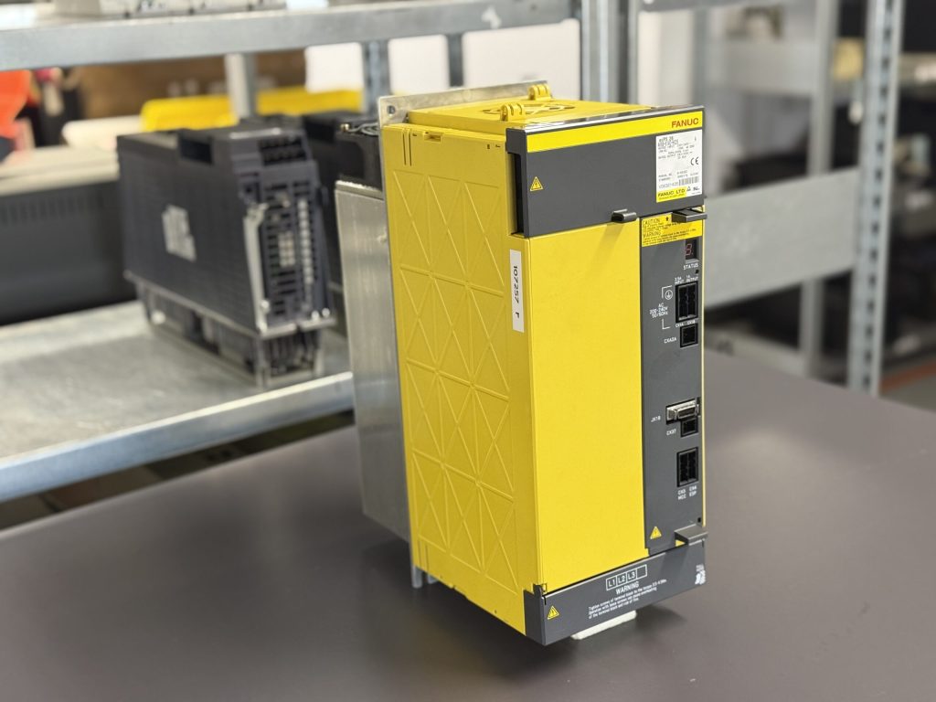
The FANUC aiPS Power Supply A06B-6140-H026 was sent in with the fault “no function”. When powered on, the unit showed no reaction at all. No status LED, no display on the 7 segment indicator, no feedback from the system.
In the machine, this type of fault typically results in a complete standstill of all axes, since the power supply for the servo amplifiers is missing.
What was noticeable is that even the basic control electronics supply was not active. Normally, even in fault conditions, a power supply module remains in an alarm state. In this case, the unit was completely dead, which already pointed to an internal power supply failure.
Incoming inspection and initial diagnosis
During incoming inspection, the external supply was checked first. The mains voltage was present and correct. The input connections were mechanically and electrically in good condition.
Next, the internal power supply was tested. It quickly became clear that no stable internal voltage was being generated. The control electronics remained completely inactive.
At the same time, the power stage was roughly checked. Initial measurements showed abnormalities in the DC link area and in the power section. This indicated a combination of supply failure and age related wear.
Technical analysis
The aiPS module is the central energy supply for the entire servo system. It generates the DC link voltage for downstream amplifiers and supplies the internal control electronics.
In this case, the root cause was found in two areas:
First, a defect in the internal power supply. This unit is responsible for supplying the control boards. If it fails, the entire module becomes inactive. Typical causes are aged components due to long term thermal stress.
Second, the power stage showed clear signs of wear. Components in the DC link and power path were significantly aged. Such damage is often caused by:
long term thermal load
mains fluctuations
high load cycles
insufficient cooling
The combination of a weakened power supply and a stressed power stage ultimately led to total failure.
A note from the manual: a drop in control voltage or problems in the DC link can lead to module failure
Repair measures and refurbishment
The unit was completely disassembled. All assemblies were cleaned and visually inspected.
The following work was carried out:
repair of the internal power supply
replacement of critical components in the supply section
rework of the power stage
replacement of all known wear components in the DC link
preventive replacement of thermally stressed components
cleaning of the cooling system
The main focus was on preventive refurbishment. The goal was not only to restore functionality but also to avoid future failures.
Final functional test
After repair, the module was tested on the test bench.
Test procedure:
power on behavior checked
stable internal supply verified
DC link voltage monitored under load
test at low load
test at medium load
simulation of load changes
thermal stability checked
The unit showed clean startup behavior. The status display worked correctly. All voltages were within specification. Even under load, the system remained stable without abnormalities.
Conclusion
The failure was caused by a defective internal power supply combined with worn components in the power stage. The “completely dead” condition is typical for this combination.
Through full refurbishment including preventive measures, the module was sustainably repaired. Preventive maintenance is especially important for such units, as many failures develop gradually over time.